G3 Made Simple
Locomotive Project No. 1
A Live Steam 0-4-4 Tank
A step-by-step construction guide provided
by our contributor "Ginger".
NEXT PART >
< PREVIOUS PART
<< Gauge3.info HOME
Part 10 : Erecting Shop
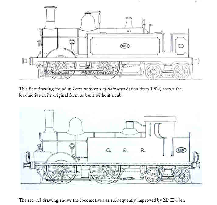
Progress on building the Q has been delayed by summer activities, decorating and holidays however the project is now back on track. This episode is all about finishing the frames wheels and bogie to prior to create a rolling chassis and attaching the cylinder. In order to speed things along and keep cost down a single cylinder is being used. Followers of the Great Eastern have been a bit neglected so the two drawings below are of the early locomotive type designed by Johnson. In all 30 engines of the "133" class were built by Neilson and Avonside in 1872/3 with 5 foot 3 inch driving wheels.
Kinking the frames
During the construction of the frames it was unclear if the frames would need to be kinked around the area of the bogie stretcher in order to provide clearance for the bogie wheels on curves. The only General Arrangement drawing to hand is for the LSWR M7 which reveals that the frames are kinked inwards by 1½ inches on each side. A simple test of the frames with the completed bogie in position revealed that the bogie wheels would indeed foul the frames when traversing a 12 foot radius curve, so the frames had to be kinked after all!
The frame kink for the model was made by pressing each frame in the vice between pressing plates made from two 2mm thick pieces of stout steel plates set 10 mm apart. The frames are held horizontally in the vice with the steel plates mounted at 90 degrees in the right place and checked with the small right angle. I decided that this would be 16 cm from the bogie end of the frame such that the kink would be concealed from view by the cab step. This simple task only takes about 15 minutes, I just hope that 2mm each side is enough. The Gauge 1 folk have designed a jig to enable this process to be achieved for the AMRIG design, but this is not really necessary if you mount the pressing plates carefully.
Bogie stretcher
The bogie needs a frame stretcher for attachment to the frames. This is made up from three slabs of brass plate 3/16 inch thick. The flat part of the stretcher is one inch wide and silver soldered to the two horizontal plates 1½ inch long by ½ inch wide which make up the sides of the stretcher. These will be attached to the frames with 8 BA screws. After silver soldering the stretcher is mounted in the mill, such that the horizontal parts can be milled absolutely flat and parallel to each other. Calculate the exact centre of the horizontal stretcher plate for the king pin from which the bogie will be suspended and drill a hole for a 6BA screw.
Two holes are then drilled on each steel frame plate to take the 8BA screws. Before drilling through to the brass stretcher check the GA drawing for the position of the bogie relative to the buffer beam. Check the model by measuring the distance from the rear buffer beam to the centre of the rear bogie wheel with the bogie resting in the correct position. Before drilling through to the horizontal parts of the brass stretcher plates it is essential to check that bearing surface is parallel to the bottom of the frames. Drill through to the brass and tap the brass stretcher 8BA. Finally open out the holes in the steel frames and insert four 8BA screws.
Time taken 1 hour 15 minutes.
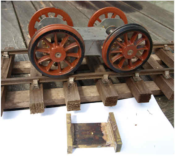
Springs for the bogie
I decided that the bogie wheels should be sprung. The easiest method would have been to fix a length of piano wire bearing down on top of the axle box, however there was not enough room, so the axle box had to be sprung from underneath. I used the short cut method of soldering a small piece of brass to the bottom of each axle box to take a 10BA thread. The four keep plates are made from suitable brass angle attached to the bogie frame with 10BA screws. The keep plates were first attached to the frames with short 10BA screws before drilling through for the hole into the axle box. Small springs were obtained kept in place by a 10BA steel washer.
Time taken 1 hour 45 minutes.
Crank axle
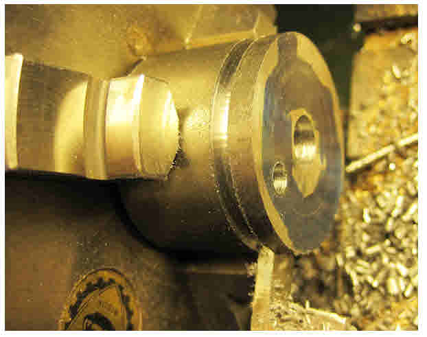
The method used to make the crank axle is very simple. Rather than cut out steel blanks to form the webs it is much easier to turn the crank webs from steel round stock using the lathe. Cut off about 1 inch of easy turning steel round stock 1¼ inch diameter. Turn the face smooth in the lathe and smear the face with marking blue. Make a small centre mark with the smallest centre drill and then mark out a circle which must not be more than 1 inch in diameter to reflect the cylinder stroke of 1 inch. The circle is made by holding a scriber in the tool post at the correct distance to engage with the surface of the steel blank and turning the chuck by hand scribing the 1 inch diameter circle.
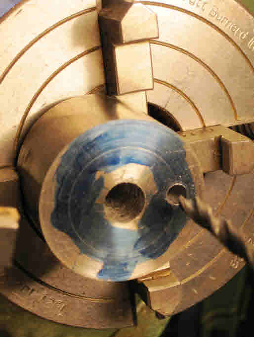
Drill the hole in the centre of the block for the drive axle at 3/8 inch diameter. In order to drill the crank pin hole mount the block in the four jaw and carefully adjust the jaws until you can touch the 1 inch diameter circle with the small diameter centre. Start drilling at the lowest speed with a larger centre and finish with a 3/16 diameter drill (see picture below).
I decided that the bogie wheels should be sprung. The easiest method would have been to fix a length of piano wire bearing down on top of the axle box, however there was not enough room, so the axle box had to be sprung from underneath. I used the short cut method of soldering a small piece of brass to the bottom of each axle box to take a 10BA thread. The four keep plates are made from suitable brass angle attached to the bogie frame with 10BA screws. The keep plates were first attached to the frames with short 10BA screws before drilling through for the hole into the axle box. Small springs were obtained kept in place by a 10BA steel washer.
Time taken 1 hour 45 minutes.
Crank axle
The method used to make the crank axle is very simple. Rather than cut out steel blanks to form the webs it is much easier to turn the crank webs from steel round stock using the lathe. Cut off about 1 inch of easy turning steel round stock 1¼ inch diameter. Turn the face smooth in the lathe and smear the face with marking blue. Make a small centre mark with the smallest centre drill and then mark out a circle which must not be more than 1 inch in diameter to reflect the cylinder stroke of 1 inch. The circle is made by holding a scriber in the tool post at the correct distance to engage with the surface of the steel blank and turning the chuck by hand scribing the 1 inch diameter circle.
Drill the hole in the centre of the block for the drive axle at 3/8 inch diameter. In order to drill the crank pin hole mount the block in the four jaw and carefully adjust the jaws until you can touch the 1 inch diameter circle with the small diameter centre. Start drilling at the lowest speed with a larger centre and finish with a 3/16 diameter drill (see picture below).
Mount the block in the 3 jaw again and part off two slices for the crank webs. I used the knife tool and cut off two slices 5/32 in thickness, again at a low speed. The crank pin was made from ¼ inch silver steel, the shoulders were turned to 3/16 by mounting in a collet to ensure accuracy and concentricity.
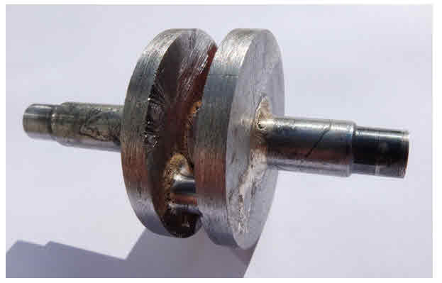
Before soldering you need to carefully determine the position of the webs on the axle with regard to the position of the centre line of the piston. The webs were threaded onto an axle with the crank pin inserted in the crank pin holes. The distance from one end of the axle is calculated by taking account of the centre line of the cylinder, the distance of the cylinder spacer at circa 3mm and allowing for the width of the axle box. In this case as I want to fit an axle pump, the distances are 26 mm from one shoulder end and 16 mm from the other. When you are quite happy and you have double checked the distance of the webs, it is time to solder up. The holes in the webs around the axle and the crank pin need to be counter sunk slightly to ensure penetration of the solder
A lot of heat is required for soldering so use a large burner. After soldering examine the job carefully and if the solder has not run into the joints, clean up the affected parts and re-solder the bits that do not look quite right. Clean up the job as best you can to check that the soldering operation is OK before the final act.
A lot of heat is required for soldering so use a large burner. After soldering examine the job carefully and if the solder has not run into the joints, clean up the affected parts and re-solder the bits that do not look quite right. Clean up the job as best you can to check that the soldering operation is OK before the final act.
Finally cut out the middle of the axle between the webs with a hack saw and carefully clean up the inner faces of the webs with files. You should now have a strong crank axle, but take care, do not drop it onto a hard floor otherwise you might have to start all over again!! Time taken should be circa 1 hour 45 minutes.
Painting the wheels
It is now time to paint the wheels prior to assembly on their axles in the near future. Cast iron wheels do go rusty quite easily, especially if subjected to a little moisture. First of all it will be necessary to fettle the wheels (old fashioned jargon for cleaning them up) with a needle file, preferably with a diamond tip type if you can get hold of one. After cleaning up the spokes and also where they meet the rim, the next step is to clean them with a most foul smelling metal degreasing liquid obtain from Phoenix & Precision Paints. This is best done outside - if the sun is shining - as they will soon dry quickly. The wheels are then spray painted with anti rust red oxide primer, one side at a time.
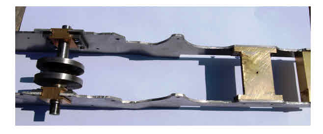
The final picture is of the kinked chassis with the bogie stretcher in place and the crank axle.
Painting the wheels
It is now time to paint the wheels prior to assembly on their axles in the near future. Cast iron wheels do go rusty quite easily, especially if subjected to a little moisture. First of all it will be necessary to fettle the wheels (old fashioned jargon for cleaning them up) with a needle file, preferably with a diamond tip type if you can get hold of one. After cleaning up the spokes and also where they meet the rim, the next step is to clean them with a most foul smelling metal degreasing liquid obtain from Phoenix & Precision Paints. This is best done outside - if the sun is shining - as they will soon dry quickly. The wheels are then spray painted with anti rust red oxide primer, one side at a time.
The final picture is of the kinked chassis with the bogie stretcher in place and the crank axle.
Next episode will be about making the big end bearing and connecting rod, fixing the cylinder in place and making the slip eccentric valve gear - ending with an air pressure test.